Driveline Angles Redux

HTML-код
- Опубликовано: 6 апр 2025
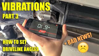
- A re-make of my most popular video. There was one common complaint about the audio quality, so in this version I stripped the music and boosted the low audio levels from the GoPro I used to record back in 2017. I've since learned a ton on how to capture better audio direct to the camera.
Spicer Driveline Angle Calculator: spicerparts.com...
Original Version is here: • Driveline Angles
The original description:
I've had several questions/discussions on driveline vibrations and how u-joint angles can contribute to those vibrations. So here's a video showing you the down and dirty on how to measure driveline angles with simple tools.
Keep in mind, I'm only focusing on u-joint angles. Driveline vibes can come from numerous sources. Out of balance wheels, bent axles, hosed up crank balancer are just a few. But assuming you've gone through the paces and checked all that stuff, and still stumped, u-joint angles could very well be the cause.


2007 Dodge Ram 1500 SLT 4x4 5.7 Hemi - Angle and Vibration Fixed! (And lessons learned, lol) As I was tracking down this phantom vibration, and my driveline angle being out of whack, I was working through replacing parts that previous owner had neglected. Lesson #1) Even if your shocks don't look that bad, they might fall into several pieces when you unbolt them. Lesson #2) I had never encountered this before, and read on a few forums that worn shocks wouldn't cause fluctuation in driveline angle, but bad shocks CAN absolutely change the angle, I replaced mine and drove around a few miles, and the angles evened out. Lesson #3) Checking the condition of motor mounts with the "P-R-N-D while holding the brake and watching for engine movement" doesn't always apply, especially with Ram 4x4s because the mounts are sometimes anchored to the front diff, which will absorb any movement caused by bad mounts, causing phantom vibrations. You have to get under there with a pry bar and check by moving things up and around, it will be very obvious if the mounts are bad. Big thanks to CJ!!! I hope this info helps somebody out there, this phantom vibration has been so annoying, so if only one person keeps their sanity because of this, I'll be happy.
Great feedback and thanks for sharing what you've learned!
Appreciate your effort! Just what I needed.
The best video on simple angle 👌 👏. Most vear off the topic explaining possibilities with considerations to everything else . Which need to be accounted for yes . But this was spot on 3 angles engine, shaft and rear pinion angle done . Brilliant.
Great video, thanks for updating the audio!
Thanks for the feedback!
On a 72 Dodge Charger I had a driveline vibration that I could not correct even with the u joint angles perfect on the horizontal plane. Eventually I found the engine/trans was not parallel with the chassis. That had the u joint angles way off on the longitudinal plane. After correcting that the vibrations were completely gone. This car had an engine swap, using the wrong engine mounts which caused the engine/trans misalignment with the chassis.
much better without the MUSIC! Great information. Thank you for info... very helpful!
Thanks for the feedback!
In the video the guy explains the slope is viewed from the front to the rear. That means even though the pinion is down it slopes up towards the rear. At least that's the way I understand it. My Harbor Freight arrows point in the direction of the slope down.
Thanks, tko 5 speed + 9in rear very helpful.
Well explained.....thanks a bunch
thank you, very helpful video, well done.
Bitchin’ tutorial. I think you would really do a lot of people some justice if you showed how to adjust four links and such.
That was a cool video!
Thanks Justin!
Thank you for putting this together. I just did a drop on my 2020 F150 (2WD, short bed) from Belltech and I got the low speed vibrations like everyone else apparently. It's Belltech kit 1001SP. Turns out I have 8.8 degrees of angle on my pinion!!!!! WTF Belltech?
great job!
I know this is an old post, but can you please explain before measuring your angles where do you zero out the angle finder or is it at zero once you turn it on. thanks,
in the online calculator you will see that the zero "tare" of the angle finder is taken the frame to mark a master datum line. And the measurments are then all relative to the frame where you zero the finder.
@ thank you.
Go Tigers! Do you have a shop? Are you located in SC?
Hey man, yeah! Go Tigers! On the shop, no, I don't have a shop, or at least a "real" shop. I farm out my services around the area though. I'm in Colorado these days. Haven't been back to SC in a long while ... Check out the Fab Forums if you haven't already. He's down around Seneca in upstate SC.
My measurements are output shaft 5 down, driveshaft 7 down, and pinion is 2 up. Spicer calculator says #1 angle is 2 degrees, and #2 angle is 9 degrees. What do I need to raise, transmission or pinion, and how many inches, lol. Help me Tom Cruise!!!!
If your pinion is up (for me that means the pinion yoke is up, higher, relative to the axle centerline) then that is actually a down slope in the spicer tool, so your angles would be 2 and 5. I'd see if you can get some axle shims to rotate the pinion a degree or two more from where it is, trying to get closer to the output shaft angle. Depending on suspension though, you may get some additional pinion rotation while under load, so you don't necessarily need to match the output shaft angle. For example, a leaf spring suspension will typically give you 1-2 or more degrees of rotation (depending on HP) on the pinion (up). So if you got to 3 or 4 degrees on your pinion you might be ok. However, the best thing is to try and get those u-joint angles to match, so if you don't/can't shim the axle, you could actually raise the output shaft to where it is closer to 4 degrees. So to really make your brain hurt ;-), with your output shaft at 4, driveshaft at 7 and pinion at 2, with 1-2 more degrees in suspension wind-up you'd have u-joint angles close to matching at ~3 degrees while under load/driving. With angles outside 2, you might get reduced life on the u-joints, but sometimes you just can't help that situation. Now, how many inches to raise, that's dependent specifically on your setup. Best I can say there is get out the trans jack and take the rear mount loose and start jacking up until you get the output shaft to 4 degrees (assuming you can w/o hitting something). Measure the gap to the rear mount and get yourself a spacer. Good luck!
@@C10CJ Thanks for the quick response, I'll let you know how it goes.
how should i measure with a double cardan joint at the transfer case end and a single ujoint at the front diff on a 2017 JK? Thanks!
I've not personally dealt with a double cardan setup. My understanding is you basically just measure driveshaft angle and then set the pinion a couple degrees less than the driveshaft, so the pinion basically points toward the transfer case vs being parallel to the output shaft (standard u-joint setup). So if your driveshaft had an angle of say 15 degrees then your pinion would be 13 degrees (pointing towards the transfer case, assuming leaf spring suspension). The front would follow the single piece driveshaft, so basically what I did in the video. The front has a tradeoff though, which is pinion angle for caster. I have limited experience on front driveshafts so I'd defer to some jeep guys that have done this a bunch as they'll have the experience on the best way to set pinion angle and caster. The tradeoff with caster is mainly steering stability in this case. As you rotate the front pinion up, you are decreasing caster, and once you go negative on caster, that's when you can get in trouble with the steering.
If the angle finder arrow pointed down on one of the readings, why would say it was actually up ?
Im lost here .
Down Up Slope ????
Hey Sho Bud ... this is one of those questions where a picture is worth a thousand words, but I can't reply with a pic so here's some words that hopefully help. First thing to keep in mind is that most of the digital angle finders I've used are really digital levels. So that little arrow is indicating which direction that end of the piece being measured needs to go to be level. So if those little arrows are on the left side of the digital angle finder, then the left side of the piece being measured needs to go up to be level if the arrow is pointing up. Now let's look at this in terms of the slope it is actually measuring. With the little arrow pointing up, that means the slope is going down from right to left. Down slope simply being the right side is higher that the left. In the case of the measurements I made in the video, the arrow was pointing up, indicating the left side, in this case let's use the driveshaft measurement, so the left side of the driveshaft (the rear U-joint) would need to go up to be level, indicating the slope is going down from the front of the vehicle to the back. Now, this works this way because I measured from the right side of the truck. If I had been measuring from the left side of the truck, the little arrow would be on the "front" side instead of the "back" side and the arrow would have been pointing down. So remember, the little arrow does not indicate slope, it indicates which way to level. Hope that helps!
Thanks for the info .
Here are the measurements i came up with on my little Toyota Corolla that came from the factory with a 2 piece shaft .
Thoes shafts are non serviceable so i had a 1 piece shaft made .
Trans Yoke was 11.7 up
Driveshaft. 11.6 up
Differential Yolk 12.5 up
I added 3° shims to raise the differential to get theses calculations .
Is this anywhere close to what its supposed to be ?
Thanks .
if this guy did not say auuummm but twice the video would be 5 min